Wheatstone's Bridge - 1
Introduction
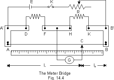
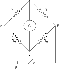
It works on the pricipal of Wheatstone bridge. It is so called because it uses a wire which is a metre long. The wire is made of uniform cross-section of a material with a high resistivity and low teemperature coefficient of resistance (e.g. manganin). The fig. 14.4 shows a simple from a Metre Bridge. The wire is streched along a metre scale between two brass or copper strips. The unknown resistance X and a known resistance R (resistance box) are connected between the gaps DF and HK, respectively. When the sliding contact (jockey) is at the position C, it divides the wire into two parts of resistance RAC and RCB; these resistance with X and R form a Wheatstone bridge.
Since the wire is uniform, therefore, RAC and RCB are proportional to l1 and l2 respectively.
Thus,

or X =

Few Important points regarding setup:-
The Balance-point is obtaained by trial and error-not by scraping the jockey along the wire.
The value of R in the resistance box should be chosen so that the balance pint comes near to the centre of the wire, i.e. from 40 cm to 60 cm from the end A.
This is because if either l1 or l2 is small, then the resistance of its end connections AA\ and BB\ will not be negligible in comparison with RAB or RCB. Hence the equation above count hold.
Dumb Question:- How has the ratio relationship obtained ?
Solution:-

The circuit is equivalent to a wheatstones bridge circuit, as shown in adjucant diagram. If current doesn't flows through the Galvanometer then the bridge is said to be balanced and for balanced bridge the relationship holds

Illustration:- The magnitude of on unknown resistance is calculated by using a metre-bridge. The first set of readings are taken by connecting the unknown resistance X in the left gap. The position of the balance point C is measured as l1 and l2 from the end A and B, respectively are taken by connecting the resistance X in the right gap. The position of the balance point C is measured as l1' and l2 from the end B and A, respectively.
The observations are recorded in the following table:
| Sl. No. | Resistance taken from R.B. R( ) ) | Balancing length | |||
|---|---|---|---|---|---|
| Unknown resistance X in right gap | Unknown resistance in the right gat | ||||
| l1 (cm) | l2 (cm) | l1 (cm) | l2 (cm) | ||
| 1 | 8 | 55.4 | 44.6 | 55.6 | 44.4 |
| 2 | 9 | 52.6 | 47.4 | 52.6 | 47.4 |
| 3 | 10 | 50.0 | 50.0 | 50.2 | 49.8 |
| 4 | 11 | 47.8 | 52.2 | 47.4 | 52.6 |
| 5 | 12 | 45.5 | 54.5 | 45.5 | 54.5 |
| 6 | 13 | 43.4 | 56.6 | 43.0 | 57.0 |